DMVPN Phase II
- By Joe Astorino
- July 17, 2017
- 1 Comment
Introduction
In this post, I am going to continue my series on DMVPN by covering DMVPN Phase II. The crypto implementation will be exactly as it was in part 1 of this series – Namely, an IKEv2 based setup using smart defaults. I won’t repeat that configuration here, but if you need to, please go back and reference the first blog post.
So, what does DMVPN Phase II bring to the table? Well, it’s a big one – we get dynamic spoke to spoke tunnels. While this sounds and is amazing, please just keep in mind that DMVPN phase II is now deprecated in favor of Phase III for a number of different reasons mainly related to scalability and design. Phase III basically accomplishes the same things as phase II, but it improves on some of the limitations we had with phase II. In this blog, we will see some of those limitations first hand
Lab Topology
We will use the same topology we did in the first part of the series. R1 is our hub and R2 and R3 are our spokes
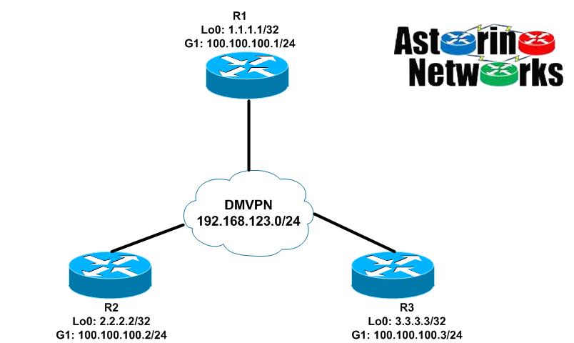
Let’s talk a little bit about the design before we jump into the configuration. First and foremost, since we want the ability to bring up dynamic spoke-to-spoke tunnels, this means that every router will be utilizing an mGRE multipoint interface. This is in contrast to what we saw in phase 1 where the hub has an mGRE interface, but the spokes were P2P going only back to the hub. Secondly, we will need to tweak our IGP a bit to make this work properly. You see, from the perspective of the routers, their tunnel interfaces are all on the same directly connected network, the 192.168.123.0/24 DMVPN overlay we have configured. As such, every router expects that it can get to every other router directly, just as if they were on the same Ethernet segment. Additionally, from a routing perspective, if we want R2 to talk directly to R3 over a dynamically created spoke-to-spoke tunnel, R2 will expect that the next-hop of any routes it learns that were advertised from R3 will be R3 and visa versa. After all, that is how it would work if the routers were really connected to the same physical network segment.
DMVPN Phase II Configuration – EIGRP
Let’s start our configuration. For now, let’s just get the hub back to exactly the way we had it for EIGRP in phase 1:
interface Tunnel0
 ip address 192.168.123.1 255.255.255.0
 no ip redirects
 no ip split-horizon eigrp 123
 ip nhrp authentication cisco
 ip nhrp map multicast dynamic
 ip nhrp network-id 123
 shutdown
 tunnel source GigabitEthernet1
 tunnel mode gre multipoint
 tunnel protection ipsec profile default
!
router eigrp 123
 network 1.0.0.0
 network 192.168.123.0
 passive-interface default
 no passive-interface Tunnel0
Notice that we have split-horizon disabled on the hub. This is for the same reason as it was in phase 1. We need the hub to learn routes from one spoke, then turn around and advertise those routes back out the tunnel interface to other spokes.
Now let’s look at a spoke. It looks basically exactly like phase I except now we have an mGRE interface on the spokes instead of p2p
interface Tunnel0
 ip address 192.168.123.2 255.255.255.0
 no ip redirects
 ip nhrp authentication cisco
 ip nhrp map 192.168.123.1 100.100.100.1
 ip nhrp map multicast 100.100.100.1
 ip nhrp network-id 123
 ip nhrp nhs 192.168.123.1
 tunnel source GigabitEthernet1
 tunnel mode gre multipoint
 tunnel protection ipsec profile default
!
router eigrp 123
 network 2.0.0.0
 network 192.168.123.0
 passive-interface default
 no passive-interface Tunnel0
R3 is going to look pretty much identical to R2. OK, so now let’s take a look and see where we are on R2
R2#sh ip route eigrp | b Gateway
Gateway of last resort is not set

      1.0.0.0/32 is subnetted, 1 subnets
D        1.1.1.1 [90/27008000] via 192.168.123.1, 00:01:02, Tunnel0
      3.0.0.0/32 is subnetted, 1 subnets
D        3.3.3.3 [90/28288000] via 192.168.123.1, 00:00:36, Tunnel0

R2#ping 3.3.3.3 so lo0
Type escape sequence to abort.
Sending 5, 100-byte ICMP Echos to 3.3.3.3, timeout is 2 seconds:
Packet sent with a source address of 2.2.2.2
!!!!!
Success rate is 100 percent (5/5), round-trip min/avg/max = 5/6/9 ms

R2#trace 3.3.3.3 so lo0
Type escape sequence to abort.
Tracing the route to 3.3.3.3
VRF info: (vrf in name/id, vrf out name/id)
  1 192.168.123.1 5 msec 5 msec 4 msec
  2 192.168.123.3 5 msec *  4 msec
Well, the little green lights are twinkling, and we can ping. We must be done, right? Wrong. Pay attention to the details. We are learning routes here on R2, but look at the next-hop of those routes. They all point to the hub, R1. Also, our trace route shows that the packets between R2 and R3 are all flowing through the hub. So, we do not have a dynamic spoke-to-spoke tunnel here. Why not? Well, let’s look at what is happening. R3 advertises a route up to R1. R1 ignores split-horizon, and sends it back out the tunnel to R2 per our configuration. When R1 does that, it changes the next-hop of the route to itself. This is how EIGRP behaves by default. However, from a logical topology perspective, that isn’t what we want here. Remember, all these routers think they are literally on the same segment of 192.168.123.0/24. Thus, if we learn a route from another spoke, it has to look like it came from that spoke. In other words, the next-hop should not change. How do we do that? We muck with our IGP. Be aware that mucking with your IGP will cause EIGRP to flap the neighbors
R1:
R1(config)#interface tunnel0
R1(config-if)#no ip next-hop-self eigrp 123

Jul 17 22:18:44.671: %DUAL-5-NBRCHANGE: EIGRP-IPv4 123: Neighbor 192.168.123.3 (Tunnel0) is down: next_hop_self value changed
Jul 17 22:18:44.671: %DUAL-5-NBRCHANGE: EIGRP-IPv4 123: Neighbor 192.168.123.2 (Tunnel0) is down: next_hop_self value changed
Jul 17 22:18:44.802: %DUAL-5-NBRCHANGE: EIGRP-IPv4 123: Neighbor 192.168.123.2 (Tunnel0) is up: new adjacency
Jul 17 22:18:44.809: %DUAL-5-NBRCHANGE: EIGRP-IPv4 123: Neighbor 192.168.123.3 (Tunnel0) is up: new adjacency
Good, now let’s check R2 again
R2#sh ip route eigrp | b Gateway
Gateway of last resort is not set

      1.0.0.0/32 is subnetted, 1 subnets
D        1.1.1.1 [90/27008000] via 192.168.123.1, 00:00:55, Tunnel0
      3.0.0.0/32 is subnetted, 1 subnets
D        3.3.3.3 [90/28288000] via 192.168.123.3, 00:00:53, Tunnel0
There we go! Notice how R3’s route now has a next-hop of R3. That’s what we want, right? right? Yes, it is, BUT…now we run into some other problems with reachability we need to talk about. So, be R2 for a minute. We want to ping 3.3.3.3. So, we look at our routing table and we see 3.3.3.3 learned from EIGRP via a next-hop of R3 at 192.168.123.3. However, 192.168.123.3 is the overlay IP address of the tunnel interface on R3. To actually get there, R2 would have to know the NBMA public IP address of R3. Why? Think about what a packet looks like going from R2 to R3. Something like this: Note, that IPsec transport mode is used here, so we don’t have an additional inside IP header like we would in tunnel mode.
[Outside IP header: 100.100.100.2 –> 100.100.100.3][ESP Header][GRE Header][Inside IP header: 2.2.2.2 –> 3.3.3.3][ICMP]
OK, great. BUT, the question is, how in the world would R2 know the real NBMA address of R3 (100.100.100.3) to be able to pull this off? It doesn’t. Check it out…
R2#show ip cef 3.3.3.3 255.255.255.255 detail
3.3.3.3/32, epoch 2
  nexthop 192.168.123.3 Tunnel0

R2#show adjacency 192.168.123.3
Protocol Interface                 Address
IP       Tunnel0                   192.168.123.3(5) (incomplete)
What is this telling us? It tells us that we know the next-hop of 3.3.3.3 is R3’s tunnel interface, 192.168.123.3. However, we don’t know how to get to that next hop, because we don’t know the NBMA address of R3. So, will this work? YES. But how does it work? Well this is where the magic of NHRP comes into play. With DMVPN phase II, as soon as we try to communicate from R2 to R3 it will trigger R2 to send an NHRP resolution request to the hub asking what R3’s NBMA (public) address is. R1 will forward this on to R3, and R3 then responds directly back to R2. R3 knows what R2’s NBMA address is at this point from the information in the NHRP request it just processed Once R2 receives the NHRP reply from R3, R2 now knows R3’s NBMA address an the two can communicate directly
Let’s see what happens
R2#ping 3.3.3.3 so lo0
Type escape sequence to abort.
Sending 5, 100-byte ICMP Echos to 3.3.3.3, timeout is 2 seconds:
Packet sent with a source address of 2.2.2.2
.!!!!
Success rate is 80 percent (4/5), round-trip min/avg/max = 3/3/5 ms

R2#trace 3.3.3.3 so lo0
Type escape sequence to abort.
Tracing the route to 3.3.3.3
VRF info: (vrf in name/id, vrf out name/id)
  1 192.168.123.3 5 msec *  4 msec

R2#sh ip nhrp
192.168.123.1/32 via 192.168.123.1
   Tunnel0 created 00:54:35, never expire
   Type: static, Flags: used
   NBMA address: 100.100.100.1
192.168.123.2/32 via 192.168.123.2
   Tunnel0 created 00:00:13, expire 01:59:46
   Type: dynamic, Flags: router unique local
   NBMA address: 100.100.100.2
    (no-socket)
192.168.123.3/32 via 192.168.123.3
   Tunnel0 created 00:00:18, expire 01:59:41
   Type: dynamic, Flags: router used nhop
   NBMA address: 100.100.100.3

R2#sh crypto ikev2 sa
 IPv4 Crypto IKEv2  SA

Tunnel-id Local                 Remote                fvrf/ivrf            Status
1         100.100.100.2/500     100.100.100.1/500     none/none            READY
      Encr: AES-CBC, keysize: 256, PRF: SHA512, Hash: SHA512, DH Grp:5, Auth sign: RSA, Auth verify: RSA
      Life/Active Time: 86400/1349 sec

Tunnel-id Local                 Remote                fvrf/ivrf            Status
2         100.100.100.2/500     100.100.100.3/500     none/none            READY
      Encr: AES-CBC, keysize: 256, PRF: SHA512, Hash: SHA512, DH Grp:5, Auth sign: RSA, Auth verify: RSA
      Life/Active Time: 86400/24 sec

 IPv6 Crypto IKEv2  SA

R2#sh crypto ipsec sa peer 100.100.100.3

interface: Tunnel0
    Crypto map tag: Tunnel0-head-0, local addr 100.100.100.2

   protected vrf: (none)
   local  ident (addr/mask/prot/port): (100.100.100.2/255.255.255.255/47/0)
   remote ident (addr/mask/prot/port): (100.100.100.3/255.255.255.255/47/0)
   current_peer 100.100.100.3 port 500
     PERMIT, flags={origin_is_acl,}
    #pkts encaps: 8, #pkts encrypt: 8, #pkts digest: 8
    #pkts decaps: 8, #pkts decrypt: 8, #pkts verify: 8
We can see that the first ping did not come back while NHRP was working it’s magic. In fact, the first packet was sent through the hub. Once NHRP sets up the rest of the control plane for us, the traffic between R2 and R3 can flow directly. We can see that after the initial ping, a traceroute goes directly between the two spokes. We also see we have IKEv2 SA and IPsec SA between the spokes and that the IPsec SA is encrypting/decrypting packets
DMVPN Phase II Configuration – OSPF
OK, let’s blow out our EIGRP configuration, and do this with OSPF as our IGP. We need to accomplish the same exact goals, but to do that, we need to understand the inner workings of OSPF and how it behaves on an NBMA type network. If you are an old school routing/switching and/or WAN guy, you might still have nightmares about how OSPF behaves over frame-relay or ATM. This is very similar. DMVPN is really just another NBMA type network just like those old protocols. Few things to keep in mind
- To preserve the next-hop addresses like we did with EIGRP is going to require OSPF network type broadcast or non-broadcast technically. Now, unless you have some very very bizarre reason to do so, you would not run network type non-broadcast here. It would require unicast neighbor commands and some other NHRP mappings. So, we will stick with OSPF network type broadcast
- An OSPF network type of broadcast is going to deman that an OSPF DR is elected. Since the hub is the only router here actually always connected to every other router, you will always want the hub to become the DR. Thus, we will make sure this is the case by setting the OSPF priority to 0 on the spokes and 255 on the hub.
R1 (hub)
interface tunnel0
 ip next-hop-self eigrp 123
 ip split-horizon eigrp 123
 ip ospf network broadcast
 ip ospf priority 255
!
no router eigrp 123
router ospf 123
 passive-interface default
 no passive-interface tunnel0
 network 1.1.1.1 0.0.0.0 area 0
 network 192.168.123.0 0.0.0.255 area 0
R2 (spoke) - Again, R3 will be almost identical here
interface tunnel0
 ip next-hop-self eigrp 123
 ip split-horizon eigrp 123
 ip ospf network broadcast
 ip ospf priority 0
!
no router eigrp 123
router ospf 123
 passive-interface default
 no passive-interface tunnel0
 network 2.2.2.2 0.0.0.0 area 0
 network 192.168.123.0 0.0.0.255 area 0
Let’s see how we did here…
R1:
R1#sh ip ospf neigh

Neighbor ID     Pri   State           Dead Time   Address         Interface
2.2.2.2           0   FULL/DROTHER    00:00:36    192.168.123.2   Tunnel0
3.3.3.3           0   FULL/DROTHER    00:00:36    192.168.123.3   Tunnel0

R1#sh ip route ospf | b Gateway
Gateway of last resort is not set

      2.0.0.0/32 is subnetted, 1 subnets
O        2.2.2.2 [110/1001] via 192.168.123.2, 00:00:23, Tunnel0
      3.0.0.0/32 is subnetted, 1 subnets
O        3.3.3.3 [110/1001] via 192.168.123.3, 00:00:13, Tunnel0
And on our R2 spoke…
R2#sh ip ospf neighbor

Neighbor ID     Pri   State           Dead Time   Address         Interface
1.1.1.1         255   FULL/DR         00:00:33    192.168.123.1   Tunnel0

R2#sh ip route ospf | b Gateway
Gateway of last resort is not set

      1.0.0.0/32 is subnetted, 1 subnets
O        1.1.1.1 [110/1001] via 192.168.123.1, 00:01:12, Tunnel0
      3.0.0.0/32 is subnetted, 1 subnets
O        3.3.3.3 [110/1001] via 192.168.123.3, 00:01:02, Tunnel0
Notice again here that the next-hop of the R3 spoke routes is R3’s tunnel address. This is what we want, and is a direct result of running OSPF network type broadcast. If we had run point-to-multipoint like we saw in phase 1, the next hop would have been changed to the hub, like we saw with EIGRP before disabling the next-hop-self.
Limitations
There are a few major concerns with DMVPN phase II that mainly relate to scalability. First, when a spoke wants to talk to another spoke, it needs to resolve the remote spoke’s NBMA address, as we have seen. In DMVPN phase II, the mechanism that kicks all that off is the fact that the next-hop of the remote spoke’s routes is the remote spoke itself. Because of this, NHRP resolution request is triggered. Therefore, regarding routes to remote spokes, we always need the next hop of the route to be the remote spoke. If that is the case, that means we really can’t do route summarization on the hub. If we did, the next-hop of the summary route would be the hub itself. So, summarization is out, which is a big deal in larger environments. Picture a DMVPN network with hundreds of sites. Every remote spoke would have to have all the routes for every other remote spoke.
Secondly, you run into efficiency issues in larger hierarchical type networks. Imagine a hierarchical topology where you have a hub and a bunch of spokes in one region, then a hub and a bunch of spokes in another region. The two regional hubs are then linked via a central hub. In other words, the regional hubs are also spokes. In that type of setup, with a phase II deployment, the packets for inter-region spoke-to-spoke traffic have to go through the cascaded hubs. For example say, spoke west1 wants to talk to spoke east 1. West1 sends the packet to the western hub. At that point, the western hub may have a static tunnel to the eastern hub, or it might build a dynamic spoke-to-spoke tunnel with it. The packet arrives at the eastern hub and is eventually delivered to spoke east1. That means the data plane for any inter-regional traffic is all centered around the hubs. This may not be efficient, and it requires the hubs to have enough horsepower and bandwidth to deal with that design.
As we will see in an upcoming post, phase III deals with both of these problems. It allows summarization, and also allows dynamic spoke-to-spoke tunnels regardless of hierarchical type designs
Summary
DMVPN phase II allows us to dynamically create spoke-to-spoke tunnels on the fly. While this method is deprecated in favor of phase III now, it is still something we need to know and understand, at least for purposes of theory and things like the CCIE lab exam. For a successful phase II implementation, we saw how it is important to understand the dynamics of the control plane. This includes our IGP of choice, as well as NHRP. As we saw in this blog, with a phase II implementation, it is the spoke that actually initiates the NHRP resolution request when it realizes that it does not have the NBMA information to get to a route’s next-hop. We also saw how it is important that the next-hop of routes advertised by a spoke remains unchanged by the hub. Both these things behave differently than what we will see with DMVPN phase III in the next post
Thanks for reading everybody and keep studying hard.
Good read