DMVPN Phase III
- By Joe Astorino
- July 18, 2017
- No Comments
Introduction
Welcome to the last installment of my series on DMVPN, which will cover DMVPN phase III. If you missed the first two blog posts covering phase I and phase II, you should check those out. I will be using the same topology and the same crypto configuration covered in the first part of this series. If you just want to cut to the chase, the crypto implementation I am using in this series is an IKEv2 setup with authentication happening by way of digital certificates.
So, DMVPN phase II already gave us dynamic spoke-to-spoke tunnels, but we also saw some scalability issues with that design. To recap, with DMVPN phase II, we could not summarize routes down from our DMVPN hub. Additionally, hierarchical type designs were a potential issue because inter-regional spoke-to-spoke traffic always had to go through the hubs. In other words, you had to daisy chain the hubs.
DMVPN phase III really accomplishes the same major goal as DMVPN phase II in that it allows us to build dynamic spoke-to-spoke tunnels. However, a major piece of our control plane (NHRP) is modified in order to make the process more efficient and scalable.
Lab Topology
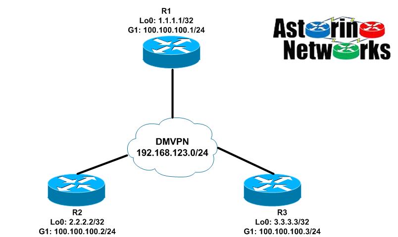
DMVPN Phase III Configuration – EIGRP
We are going to build this configuration in steps to full grasp what is going on. Let’s start with something that looks similar to phase 1 except that we will continue to have mGRE interfaces on the spokes as well
R1 (hub)
interface Tunnel0
 ip address 192.168.123.1 255.255.255.0
 no ip redirects
 no ip split-horizon eigrp 123
 ip nhrp authentication cisco
 ip nhrp map multicast dynamic
 ip nhrp network-id 123
 tunnel source GigabitEthernet1
 tunnel mode gre multipoint
 tunnel protection ipsec profile default
!
router eigrp 123
 network 1.0.0.0
 network 192.168.123.0
 passive-interface default
 no passive-interface Tunnel0
Here is one of our spokes, R2:
interface Tunnel0
 ip address 192.168.123.2 255.255.255.0
 no ip redirects
 ip nhrp authentication cisco
 ip nhrp map 192.168.123.1 100.100.100.1
 ip nhrp map multicast 100.100.100.1
 ip nhrp network-id 123
 ip nhrp nhs 192.168.123.1
 tunnel source GigabitEthernet1
 tunnel mode gre multipoint
 tunnel protection ipsec profile default
!
router eigrp 123
 network 2.0.0.0
 network 192.168.123.0
 passive-interface default
 no passive-interface Tunnel0
Let’s have a look around on R2
R2#sh ip route eigrp | b Gateway
Gateway of last resort is not set

      1.0.0.0/32 is subnetted, 1 subnets
D        1.1.1.1 [90/27008000] via 192.168.123.1, 00:03:14, Tunnel0
      3.0.0.0/32 is subnetted, 1 subnets
D        3.3.3.3 [90/28288000] via 192.168.123.1, 00:03:34, Tunnel0

R2#ping 3.3.3.3 so lo0
Type escape sequence to abort.
Sending 5, 100-byte ICMP Echos to 3.3.3.3, timeout is 2 seconds:
Packet sent with a source address of 2.2.2.2
!!!!!
Success rate is 100 percent (5/5), round-trip min/avg/max = 6/6/9 ms

R2#trace 3.3.3.3 so lo0
Type escape sequence to abort.
Tracing the route to 3.3.3.3
VRF info: (vrf in name/id, vrf out name/id)
  1 192.168.123.1 5 msec 4 msec 5 msec
  2 192.168.123.3 4 msec *  5 msec
So, this looks an awfully lot like DMVPN phase 1, right? Notice the next-hop of 3.3.3.3 is the hub’s tunnel address, 192.168.123.1. At this point, we have reachability, but all traffic goes through the hub. We will never build a dynamic spoke-to-spoke tunnel with this setup. Why? Recall what triggered the NHRP resolution request in DMVPN phase II. It was the fact that the next-hop was the tunnel address of the remote spoke, and the fact that we did not know the NBMA of that remote spoke. In this case, the problem doesn’t exist. The next hop is the hub, and we already know the NBMA of the hub via a static NHRP mapping configured on the spoke. Thus, when R2 wants to talk to 3.3.3.3, it simply routes it to the hub. The hub then follows it’s routing table, and routes the packet back out the tunnel down to R3. Nothing magical here.
This is where DMVPN phase III comes into play. The good news is that to make our existing configuration a phase III deployment, we literally need to add two commands
R1:
R1(config)#interface tun0
R1(config-if)#ip nhrp redirect
R2:
R2(config)#int tun0
R2(config-if)#ip nhrp shortcut
R3:
R3(config)#int tun0
R3(config-if)#ip nhrp shortcut
Now, let’s see what happens on R2:
R2#trace 3.3.3.3 so lo0
Type escape sequence to abort.
Tracing the route to 3.3.3.3
VRF info: (vrf in name/id, vrf out name/id)
  1 192.168.123.1 6 msec 4 msec 5 msec
  2 192.168.123.3 6 msec

R2#trace 3.3.3.3 so lo0
Type escape sequence to abort.
Tracing the route to 3.3.3.3
VRF info: (vrf in name/id, vrf out name/id)
  1 192.168.123.3 4 msec *  4 msec

R2#sh ip nhrp
2.2.2.2/32 via 192.168.123.2
   Tunnel0 created 00:00:20, expire 01:59:40
   Type: dynamic, Flags: router unique local
   NBMA address: 100.100.100.2
    (no-socket)
3.3.3.3/32 via 192.168.123.3
   Tunnel0 created 00:00:20, expire 01:59:40
   Type: dynamic, Flags: router rib nho
   NBMA address: 100.100.100.3
192.168.123.1/32 via 192.168.123.1
   Tunnel0 created 05:15:21, never expire
   Type: static, Flags: used
   NBMA address: 100.100.100.1
192.168.123.3/32 via 192.168.123.3
   Tunnel0 created 00:00:20, expire 01:59:40
   Type: dynamic, Flags: router nhop rib
   NBMA address: 100.100.100.3

R2#sh crypto ikev2 sa
 IPv4 Crypto IKEv2  SA

Tunnel-id Local                 Remote                fvrf/ivrf            Status
1         100.100.100.2/500     100.100.100.1/500     none/none            READY
      Encr: AES-CBC, keysize: 256, PRF: SHA512, Hash: SHA512, DH Grp:5, Auth sign: RSA, Auth verify: RSA
      Life/Active Time: 86400/2268 sec

Tunnel-id Local                 Remote                fvrf/ivrf            Status
3         100.100.100.2/500     100.100.100.3/500     none/none            READY
      Encr: AES-CBC, keysize: 256, PRF: SHA512, Hash: SHA512, DH Grp:5, Auth sign: RSA, Auth verify: RSA
      Life/Active Time: 86400/28 sec

 IPv6 Crypto IKEv2  SA

R2#sh crypto ipsec sa peer 100.100.100.3

interface: Tunnel0
    Crypto map tag: Tunnel0-head-0, local addr 100.100.100.2

   protected vrf: (none)
   local  ident (addr/mask/prot/port): (100.100.100.2/255.255.255.255/47/0)
   remote ident (addr/mask/prot/port): (100.100.100.3/255.255.255.255/47/0)
   current_peer 100.100.100.3 port 500
     PERMIT, flags={origin_is_acl,}
    #pkts encaps: 6, #pkts encrypt: 6, #pkts digest: 6
    #pkts decaps: 4, #pkts decrypt: 4, #pkts verify: 4
We see that the first traceroute still had packets going through the hub. However, immediately after that we run another traceroute and we have a dynamic spoke-to-spoke tunnel. We can then see that we have an NHRP entry mapping R3’s tunnel address to it’s NBMA (public) address and that we have an IPsec SA between the two spokes. Success!
Let’s take a look at R2’s routing table now
R2#sh ip route | b Gateway
Gateway of last resort is not set

      1.0.0.0/32 is subnetted, 1 subnets
D        1.1.1.1 [90/27008000] via 192.168.123.1, 00:13:59, Tunnel0
      2.0.0.0/32 is subnetted, 1 subnets
C        2.2.2.2 is directly connected, Loopback0
      3.0.0.0/32 is subnetted, 1 subnets
D   %    3.3.3.3 [90/28288000] via 192.168.123.1, 00:14:19, Tunnel0
      100.0.0.0/8 is variably subnetted, 2 subnets, 2 masks
C        100.100.100.0/24 is directly connected, GigabitEthernet1
L        100.100.100.2/32 is directly connected, GigabitEthernet1
      192.168.123.0/24 is variably subnetted, 3 subnets, 2 masks
C        192.168.123.0/24 is directly connected, Tunnel0
L        192.168.123.2/32 is directly connected, Tunnel0
H        192.168.123.3/32 is directly connected, 00:04:18, Tunnel0
Notice the “%” symbol next to the 3.3.3.3 route. This means “next hop override”, and we’ll talk more about it in a second. Also notice the NHRP (H) route for R3’s tunnel address.
So what exactly changed? How did this all the sudden magically start working? Well, we want the next-hop of remote spoke routes to be the hub. That way, we can do summarization if we want to later on. However, based on what we know so far, if we do that, we will never trigger an NHRP resolution request on the initiating spoke, right (think phase II)? So, the question becomes, how do we allow the next hop to remain the hub, but also kick off an NHRP resolution request? The answer is the NHRP redirect
Here is what happens, when we put ip nhrp redirect on the hub’s tunnel interface. When R2 wants to send a packet to 3.3.3.3, it looks in it’s routing table and sees the next-hop is the hub. We also have the NBMA address of the hub from our ip nhrp map command, so there is no problem – R2 simply routes the packet to the hub, R1. R1 receives the packet on it’s tunnel interface, then turns around and sends that packet right back out the same interface down to R3. Again, the first packet is routed through the hub, just like phase II. At that point, NHRP redirect kicks in. When R1 realizes it is sending a packet back out the same interface it received it on, R1 sends an NHRP redirect message back to R2 saying “Go ahead and do an NHRP resolution request for 3.3.3.3”. At that point, R2 sends the NHRP resolution request for 3.3.3.3 up to the hub. The hub forwards the request on to R3. R3 now knows the NBMA address of R2 because that information was in the NHRP request. So, R3 answers the NHRP request from R2 directly.
Now, here is where the magic of NHRP shortcut kicks in. When R2 receives the NHRP reply back from R3, it installs a “next hop override” for the 3.3.3.3 route as well as an NHRP route for R3’s tunnel address. Essentially, the next hop override says “I know my routing table says the next-hop for 3.3.3.3/32 is the hub at 192.168.123.1, but override that…in reality it is 192.168.123.3. Check it out…
R2:
R2#sh ip route 3.3.3.3
Routing entry for 3.3.3.3/32
  Known via "eigrp 123", distance 90, metric 28288000, type internal
  Redistributing via eigrp 123
  Last update from 192.168.123.1 on Tunnel0, 00:40:48 ago
  Routing Descriptor Blocks:
  * 192.168.123.1, from 192.168.123.1, 00:40:48 ago, via Tunnel0
      Route metric is 28288000, traffic share count is 1
      Total delay is 105000 microseconds, minimum bandwidth is 100 Kbit
      Reliability 255/255, minimum MTU 1476 bytes
      Loading 1/255, Hops 2

R2#sh ip cef 3.3.3.3 255.255.255.255 detail
3.3.3.3/32, epoch 2, flags [rib only nolabel, rib defined all labels]
  nexthop 192.168.123.3 Tunnel0

R2#sh ip route 192.168.123.3
Routing entry for 192.168.123.3/32
  Known via "nhrp", distance 250, metric 255 (connected, via interface)
  Last update from 192.168.123.3 on Tunnel0, 00:07:52 ago
  Routing Descriptor Blocks:
  * 192.168.123.3, from 192.168.123.3, 00:07:52 ago, via Tunnel0
      Route metric is 255, traffic share count is 1
      MPLS label: none
Basically what this is telling us is that despite EIGRP telling us the next-hop is the hub, we are overriding that in the CEF table with a next-hop of the remote spoke, R3. We know how to get to the real next-hop by way of the mapping provided by NHRP.
Now that we have the idea down, let’s configure some summarization. We will keep it simple and just configure a default summary route on the hub. In a real world deployment, where the remote spokes are indeed stubs, EIGRP stub feature would also be a good idea.
R1(config)#int tun0
R1(config-if)#ip summary-address eigrp 123 0.0.0.0 0.0.0.0
R1(config-if)#
Jul 18 04:00:24.354: %DUAL-5-NBRCHANGE: EIGRP-IPv4 123: Neighbor 192.168.123.3 (Tunnel0) is resync: summary configured
Jul 18 04:00:24.355: %DUAL-5-NBRCHANGE: EIGRP-IPv4 123: Neighbor 192.168.123.2 (Tunnel0) is resync: summary configured
I also went ahead and cleared the NHRP mappings on both spokes
R2#sh ip route | b Gateway
Gateway of last resort is 192.168.123.1 to network 0.0.0.0

D*    0.0.0.0/0 [90/27008000] via 192.168.123.1, 00:03:06, Tunnel0
      2.0.0.0/32 is subnetted, 1 subnets
C        2.2.2.2 is directly connected, Loopback0
      100.0.0.0/8 is variably subnetted, 2 subnets, 2 masks
C        100.100.100.0/24 is directly connected, GigabitEthernet1
L        100.100.100.2/32 is directly connected, GigabitEthernet1
      192.168.123.0/24 is variably subnetted, 2 subnets, 2 masks
C        192.168.123.0/24 is directly connected, Tunnel0
L        192.168.123.2/32 is directly connected, Tunnel0
Notice that we only have the EIGRP summary route now. We don’t have the remote spoke network. Since I cleared the NHRP tables, my NHRP route and next-hop override went away. Let’s ping again…
R2#ping 3.3.3.3 so lo0
Type escape sequence to abort.
Sending 5, 100-byte ICMP Echos to 3.3.3.3, timeout is 2 seconds:
Packet sent with a source address of 2.2.2.2
!!!!!
Success rate is 100 percent (5/5), round-trip min/avg/max = 4/5/8 ms

R2#trace 3.3.3.3 so lo0
Type escape sequence to abort.
Tracing the route to 3.3.3.3
VRF info: (vrf in name/id, vrf out name/id)
  1 192.168.123.3 5 msec *  4 msec

R2#sh ip route | b Gateway
Gateway of last resort is 192.168.123.1 to network 0.0.0.0

D*    0.0.0.0/0 [90/27008000] via 192.168.123.1, 00:04:21, Tunnel0
      2.0.0.0/32 is subnetted, 1 subnets
C        2.2.2.2 is directly connected, Loopback0
      3.0.0.0/32 is subnetted, 1 subnets
H        3.3.3.3 [250/255] via 192.168.123.3, 00:00:13, Tunnel0
      100.0.0.0/8 is variably subnetted, 2 subnets, 2 masks
C        100.100.100.0/24 is directly connected, GigabitEthernet1
L        100.100.100.2/32 is directly connected, GigabitEthernet1
      192.168.123.0/24 is variably subnetted, 3 subnets, 2 masks
C        192.168.123.0/24 is directly connected, Tunnel0
L        192.168.123.2/32 is directly connected, Tunnel0
H        192.168.123.3/32 is directly connected, 00:00:13, Tunnel0
Notice, we have a bit of a change. Before we did the summarization, we already had an EIGRP route for 3.3.3.3/32 with an AD of 90. Therefore, the NHRP route for 3.3.3.3 was not inserted into the routing table since NHRP has an AD of 250. Thus, we had the next-hop override behavior and only an NHRP route for the remote spoke tunnel address. In the case of summarization, we never had an EIGRP route for 3.3.3.3 to begin with. Therefore, the NHRP routes for both 3.3.3.3 and 192.168.123.3 get added to the routing table. In other words, there is no reason to do a next hop override.
DMVPN Phase III Configuration – OSPF
Let’s port this configuration over to OSPF. Much like phase I and phase II, there are some considerations for OSPF with phase III as well. Remember, when a spoke advertises a route to the hub, we want the hub to change the next-hop to itself before sending the route down to the other spoke. To do that, the best recipe will be OSPF network type point-to-multipoint, which is not the default (point-to-point is the default OSPF network type on a GRE interface).
R1(config)#int tun0
R1(config-if)#ip split-horizon eigrp 123
R1(config-if)#no ip summary-address eigrp 123 0.0.0.0 0.0.0.0
R1(config-if)#ip ospf network point-to-multipoint
R1(config-if)#exit
R1(config)#no router eigrp 123
R1(config)#router ospf 123
R1(config-router)#network 1.1.1.1 0.0.0.0 area 0
R1(config-router)#network 192.168.123.0 0.0.0.255 area 0
R2(config)#int tun0
R2(config-if)#ip ospf network point-to-multipoint
R2(config-if)#exit
R2(config)#no router eigrp 123
R2(config)#router ospf 123
R2(config-router)#network 2.2.2.2 0.0.0.0 area 0
R2(config-router)#network 192.168.123.0 0.0.0.255 area 0
R3(config)#int tun0
R3(config-if)#ip ospf network point-to-multipoint
R3(config-if)#exit
R3(config)#no router eigrp 123
R3(config)#router ospf 123
R3(config-router)#network 3.3.3.3 0.0.0.0 area 0
R3(config-router)#network 192.168.123.0 0.0.0.255 area 0
Let’s check out one of our spokes, R2:
R2#sh ip route ospf | b Gateway
Gateway of last resort is not set

      1.0.0.0/32 is subnetted, 1 subnets
O        1.1.1.1 [110/1001] via 192.168.123.1, 00:16:41, Tunnel0
      3.0.0.0/32 is subnetted, 1 subnets
O        3.3.3.3 [110/2001] via 192.168.123.1, 00:16:41, Tunnel0
      192.168.123.0/24 is variably subnetted, 4 subnets, 2 masks
O        192.168.123.1/32 [110/1000] via 192.168.123.1, 00:16:41, Tunnel0
O        192.168.123.3/32 [110/2000] via 192.168.123.1, 00:16:41, Tunnel0
Looks good. Let’s try a ping over to R3 again
R2#ping 3.3.3.3 so lo0
Type escape sequence to abort.
Sending 5, 100-byte ICMP Echos to 3.3.3.3, timeout is 2 seconds:
Packet sent with a source address of 2.2.2.2
!!!!!
Success rate is 100 percent (5/5), round-trip min/avg/max = 5/9/18 ms

R2#trace 3.3.3.3 so lo0
Type escape sequence to abort.
Tracing the route to 3.3.3.3
VRF info: (vrf in name/id, vrf out name/id)
  1 192.168.123.3 4 msec *  4 msec

R2#sh ip route | b Gateway
Gateway of last resort is not set

      1.0.0.0/32 is subnetted, 1 subnets
O        1.1.1.1 [110/1001] via 192.168.123.1, 00:18:12, Tunnel0
      2.0.0.0/32 is subnetted, 1 subnets
C        2.2.2.2 is directly connected, Loopback0
      3.0.0.0/32 is subnetted, 1 subnets
O   %    3.3.3.3 [110/2001] via 192.168.123.1, 00:18:12, Tunnel0
      100.0.0.0/8 is variably subnetted, 2 subnets, 2 masks
C        100.100.100.0/24 is directly connected, GigabitEthernet1
L        100.100.100.2/32 is directly connected, GigabitEthernet1
      192.168.123.0/24 is variably subnetted, 4 subnets, 2 masks
C        192.168.123.0/24 is directly connected, Tunnel0
O        192.168.123.1/32 [110/1000] via 192.168.123.1, 00:18:12, Tunnel0
L        192.168.123.2/32 is directly connected, Tunnel0
O   %    192.168.123.3/32 [110/2000] via 192.168.123.1, 00:18:12, Tunnel0
We have slightly different behavior here with OSPF, but the concepts are the same. Because of how point-to-multipoint works with OSPF, we already had a /32 route for the remote spoke tunnel address before doing the ping. Therefore, you now notice we have two next-hop overrides from the NHRP process. First, we have 3.3.3.3 shown with a next-hop of 192.168.123.1 (the hub) in the routing table, but with a next-hop override. In reality, the next-hop inserted into the CEF table by way of the NHRP reply / shortcut is R3, 192.168.123.3. Secondly, we have an override for the next-hop itself. In other words, OSPF is telling us the to get to 192.168.123.3 send packets to the hub, 192.168.123.1. However the next-hop override basically says if we want to get to 192.168.123.3, resolve that through NHRP.
We can do some summarization, but it gets a little trickier with OSPF. With OSPF, you can summarize between areas at an ABR, or you can summarize external routes that have been redistributed on an ASBR. We only currently have a single area 0 in our setup.
DMVPN Phase III Scalability
Scalability is the big thing with phase III. We have already seen how the hub now has the ability to summarize routes, which in itself is huge. Another advantage of phase III comes with hierarchical type designs. Because of the way phase III designed, remote sites that are spokes off of different hubs can build direct spoke-to-spoke tunnels with each other. This was not possible in DMVPN phase II where you would have had to daisy chain your hubs.
Summary
In this post, we saw how DMVPN phase III builds on DMVPN phase II. Like phase II, it allows dynamic spoke-to-spoke tunnels to be built. However, it improves on phase II by allowing route summarization and by allow dynamic spoke-to-spoke tunnels between spokes in an hierarchical design. There are a few keys to a successful phase III setup. First, you want the next hop of remote spoke routes to be the hub, so make sure your IGP is configured properly for that. Secondly, NHRP redirect should be placed on the hub, and NHRP shortcut should be placed on the spokes. The NHRP redirect/shortcut is the magic that makes it a phase III design. Hope this helped out, and thanks for reading
Leave a Reply