DMVPN Phase I
- By Joe Astorino
- July 17, 2017
- 1 Comment
Introduction
In this blog, we will take a look at DMVPN phase I, exploring what exactly it is, how it works, and configuring it in a lab environment. Dynamic multipoint VPN, or DMVPN as it is more affectionately known, is a matured, very densely deployed technology at this point. It’s primary purpose is very generally speaking, to dynamically nail up overlay VPN tunnels across a (usually) public network infrastructure (like the internet). Depending on the implementation details, these tunnels can be between a remote spoke site and a main hub site, or actually between spokes themselves. These tunnels can and usually are secured with IPsec. High availability designs that include multiple hubs are also possible and supported through a couple different well known designs. This blog will not be an exhaustive technical overview of GRE, NHRP, IPsec, IGP routing, etc. It is assumed the reader is fairly familiar with these things already.
There are three phases of DMVPN:
- Phase I – Strictly a hub and spoke topology. Spokes have P2P GRE tunnels to the hub with statically defined tunnel destinations. Hub has a single mGRE tunnel interface. All inter-spoke traffic must transit through the hub. This is less efficient for spoke to spoke communication, but forces all traffic through the hub, which may be what you want from a security perspective.
- Phase II – Legacy design that allows for direct spoke-to-spoke tunnels. There are technical limitations and scalability challenges with phase 2, as it does not allow for route summarization at the hub, and in a hierarchical type design, inter-region spoke traffic must always transit the regional hubs
- Phase III – Allows for direct spoke-to-spoke tunnels in a more scalable manner than phase II. Allows for summarization at the hub, and for direct spoke-to-spoke tunnels even between spokes in different regions in a hierarchical design. This is the preferred method in a deployment requiring direct spoke to spoke tunnels
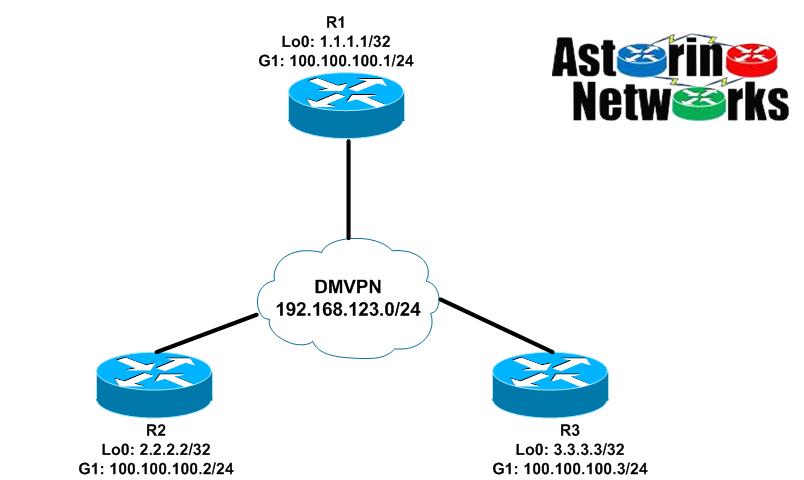
Lab Topology
As you can see below, our lab topology is pretty straight forward. R1 will act as our hub, while R2 and R3 will be spokes. The topology diagram depicts the logical DMVPN overlay network we are trying to build here. For simplicity, the “public” GigabitEthernet1 interfaces of all the routers are on the same VLAN and subnet, 100.100.100.0/24. The overlay DMVPN network we are building through the physical infrastructure is the 192.168.123.0/24 neetwork
In our DMVPN phase I design here, we will have a P2P GRE tunnel interface on both spokes R2 and R3 that terminate on the hub, R1. R1 will have a single mGRE tunnel interface that allows it to connect to both spokes. We will do an implementation using EIGRP to start, and then show an implementation using OSPF.
The Crypto: IKEv2 with DMVPN?
Traditionally, most of us are probably used to dealing with IKEv1 and IPsec in conjunction with DMVPN. While this is fine, IKEv2 is the up and coming thing, and offers some pretty cool new features. For this blog, we will be implementing the IPsec piece using IKEv2 as the key management protocol. But, doesn’t that make it FlexVPN? Not really. One can accomplish similar goals with FlexVPN using designs that include IKEv2 and other things like Flex server/client and flex mesh, but that is not what we are doing here. We are doing DMVPN just like we always have, but using IKEv2 to negotiate IPsec SA’s. Specifically, we will be using digital certificates for authentication. R1 doubles as a CA server. So, here are our relevant configurations
We will start with our PKI configuration. Note that before bringing the CA online, I manually generated a 4096-bit RSA keypair called “ROOT_CA_KEYS”. I then generated another RSA key pair called “MYKEYS” and enrolled R1 with itself. Basically, R1 is setup to receive a signed certificate to be used for authentication from itself.
R1:
crypto pki server ROOT_CA
 no database archive
 issuer-name CN=r1.lab.local
 grant auto
 hash sha512
!
crypto pki trustpoint ROOT_CA
 revocation-check crl
 rsakeypair ROOT_CA_KEYS
!
crypto pki trustpoint CA
 enrollment url http://100.100.100.1:80
 fqdn r1.lab.local
 revocation-check none
 rsakeypair MYKEYS
R2:
crypto pki trustpoint CA
 enrollment url http://100.100.100.1:80
 fqdn r2.lab.local
 revocation-check none
 rsakeypair MYKEYS
R3:
crypto pki trustpoint CA
 enrollment url http://100.100.100.1:80
 fqdn r3.lab.local
 revocation-check none
 rsakeypair MYKEYS
After this step, we issue the command crypto pki authenticate CA and crypto pki enroll CA on each router. The first command pulls the CA root certificate down to the router, while the second command requests that the CA issue a certificate to the router using SCEP. At this stage, we have the root CA certificate and certificate to be used for authentication on each router. Here is R2 for example
R2#sh crypto pki certificates CA
Certificate
  Status: Available
  Certificate Serial Number (hex): 08
  Certificate Usage: General Purpose
  Issuer:
    cn=r1.lab.local
  Subject:
    Name: r2.lab.local
    hostname=r2.lab.local
  Validity Date:
    start date: 05:33:04 UTC Jul 17 2017
    end   date: 05:33:04 UTC Jul 17 2018
  Associated Trustpoints: CA
  Storage: nvram:r1lablocal#8.cer

CA Certificate
  Status: Available
  Certificate Serial Number (hex): 01
  Certificate Usage: Signature
  Issuer:
    cn=r1.lab.local
  Subject:
    cn=r1.lab.local
  Validity Date:
    start date: 04:30:27 UTC Jul 17 2017
    end   date: 04:30:27 UTC Jul 16 2020
  Associated Trustpoints: CA
  Storage: nvram:r1lablocal#1CA.cer
Ok, now the fun part, the IKEv2 implementation. IKEv2 smart defaults really allows us to do the bare minimum amount of work here. Here is R1’s configuration. R2 and R3 are identical except for the local identity FQDN. Ultimately, we will end up binding the default IPsec profile to the tunnel interfaces we create in a bit. That is pretty much it for the crypto. Pretty cool huh? Behind the scenes, IKEv2 is actually using the default IKEv2 proposal, policy, and transform-sets.
crypto ikev2 profile IKEv2-PROFILE
 match identity remote fqdn domain lab.local
 identity local fqdn r1.lab.local
 authentication local rsa-sig
 authentication remote rsa-sig
 pki trustpoint CA
!
crypto ipsec profile default
 set ikev2-profile IKEv2-PROFILE
In the above configuration, we are saying to use this IKEv2 profile if the remote end sends an IKE ID of type FQDN that contains the domain lab.local. We then tell the router itself to send an IKE ID of type FQDN and what that IKE ID should be. Finally, we tell the router that both the local and remote routers will be authenticated using digital certificates, and what the associated trustpoint should be.
A little more detail on smart defaults: The default ikev2 proposal is used to setup the crypto for IKEv2 SA_INIT, which is sort of like IKEv1 MM1 – MM4 in that it establishes the crypto algorithms used to secure the IKEv2 SA and then does a DH key exchange. The default IKEv2 policy calls the default proposal. The default IPsec transform set establishes what crypto algorithms we will use to secure the actual IPsec SA. Finally, the default IPsec profile calls the default transform-set. All we really had to do was create the IKEv2 profile and associate it with the IPsec profile.
R1#sh crypto ikev2 proposal default
 IKEv2 proposal: default
     Encryption : AES-CBC-256 AES-CBC-192 AES-CBC-128
     Integrity  : SHA512 SHA384 SHA256 SHA96 MD596
     PRF        : SHA512 SHA384 SHA256 SHA1 MD5
     DH Group   : DH_GROUP_1536_MODP/Group 5 DH_GROUP_1024_MODP/Group 2

R1#sh crypto ikev2 policy default
 IKEv2 policy : default
      Match fvrf : any
      Match address local : any
      Proposal    : default

R1#sh crypto ipsec transform-set  default
{ esp-aes esp-sha-hmac  }
   will negotiate = { Transport,  },

R1#sh crypto ipsec profile default
IPSEC profile default
        IKEv2 Profile: IKEv2-PROFILE
        Security association lifetime: 4608000 kilobytes/3600 seconds
        Responder-Only (Y/N): N
        PFS (Y/N): N
        Mixed-mode : Disabled
        Transform sets={
                default:  { esp-aes esp-sha-hmac  } ,
        }
DMVPN Phase 1: EIGRP
OK, now that we have the crypto out of the way and primed, let’s focus on the actual DMVPN implementation. We will start with the hub, R1
R1:
interface Tunnel0
 ip address 192.168.123.1 255.255.255.0
 no ip redirects
 no ip split-horizon eigrp 123
 ip nhrp authentication cisco
 ip nhrp map multicast dynamic
 ip nhrp network-id 123
 tunnel source GigabitEthernet1
 tunnel mode gre multipoint
 tunnel protection ipsec profile default
!
router eigrp 123
 network 1.0.0.0
 network 192.168.123.0
 passive-interface default
 no passive-interface Tunnel0
A few key commands here to understand:
no ip split-horizon eigrp 123 – This disables split horizon on the hub. Remember, in phase I all control plane and data plane traffic goes through the hub. That includes our routing protocol. In this case, spokes will advertise their routes to the hub, who will learn those routes on the mGRE tunnel interface. By default, split horizon prohibits the hub from advertising routes learned from one spoke back out the tunnel interface to other spokes. Thus, without this switch, spokes will never learn each other’s routes.
ip nhrp map multicast dynamic – Basically says that if any multicast traffic is required to go out the tunnel, send that traffic individually to each spoke that has registered dynamically to the hub via NHRP. This is mostly for our routing protocols like EIGRP and OSPF
tunnel mode gre multipoint – This is a multipoint GRE tunnel. From the perspective of the hub, it is on the same overlay network as all the spokes, 192.168.123.0/24
tunnel protection ipsec profile default – Applying the crypto we configured earlier to protect the tunnels
Let’s take a look at a spoke.
R2:
interface Tunnel0
 ip address 192.168.123.2 255.255.255.0
 ip nhrp authentication cisco
 ip nhrp map 192.168.123.1 100.100.100.1
 ip nhrp map multicast 100.100.100.1
 ip nhrp network-id 123
 ip nhrp nhs 192.168.123.1
 tunnel source GigabitEthernet1
 tunnel destination 100.100.100.1
 tunnel protection ipsec profile default

router eigrp 123
 network 2.0.0.0
 network 192.168.123.0
 passive-interface default
 no passive-interface Tunnel0
ip nhrp map – This maps the private tunnel IP address of the NHRP NHS to the NBMA “public” address
ip nhrp map multicast – This maps multicast traffic to the hub. In other words, if we have multicast traffic like for EIGRP, encapsulate it in GRE/IPsec and send to the hub
ip nhrp nhs – Defines the hub as the NHRP NHS where we will register
Notice there is no tunnel mode set. This is because the spokes are P2P GRE interfaces, which is the default mode. R3’s configuration is going to be almost identical, aside from the router specific IP addresses, EIGRP networks, etc.
Verification
Checking the hub:
R1#sh crypto ikev2 sa
 IPv4 Crypto IKEv2  SA

Tunnel-id Local                 Remote                fvrf/ivrf            Status
2         100.100.100.1/500     100.100.100.3/500     none/none            READY
      Encr: AES-CBC, keysize: 256, PRF: SHA512, Hash: SHA512, DH Grp:5, Auth sign: RSA, Auth verify: RSA
      Life/Active Time: 86400/43780 sec

Tunnel-id Local                 Remote                fvrf/ivrf            Status
1         100.100.100.1/500     100.100.100.2/500     none/none            READY
      Encr: AES-CBC, keysize: 256, PRF: SHA512, Hash: SHA512, DH Grp:5, Auth sign: RSA, Auth verify: RSA
      Life/Active Time: 86400/43801 sec

 IPv6 Crypto IKEv2  SA

R1#sh ip nhrp
192.168.123.2/32 via 192.168.123.2
   Tunnel0 created 12:16:29, expire 01:43:30
   Type: dynamic, Flags: unique registered used nhop
   NBMA address: 100.100.100.2

192.168.123.3/32 via 192.168.123.3
   Tunnel0 created 12:16:08, expire 01:43:51
   Type: dynamic, Flags: unique registered used nhop
   NBMA address: 100.100.100.3

R1#sh ip eigrp neigh
EIGRP-IPv4 Neighbors for AS(123)
H   Address                 Interface              Hold Uptime   SRTT   RTO  Q  Seq
                                                   (sec)         (ms)       Cnt Num
1   192.168.123.3           Tu0                      13 12:09:45   11  1470  0  6
0   192.168.123.2           Tu0                      13 12:10:03   37  1470  0  15

R1#sh ip route eigrp | b Gateway
Gateway of last resort is not set

      2.0.0.0/32 is subnetted, 1 subnets
D        2.2.2.2 [90/27008000] via 192.168.123.2, 12:11:34, Tunnel0
      3.0.0.0/32 is subnetted, 1 subnets
D        3.3.3.3 [90/27008000] via 192.168.123.3, 12:11:15, Tunnel0
Looks like our hub is up. We have IKEv2 SA’s and EIGRP neighbors with each spoke, and we have our spoke routes. We can also see that the spokes have registered their NBMA addresses with the hub via NHRP. Let’s see R2 and do some tests
R2#sh ip eigrp neigh
EIGRP-IPv4 Neighbors for AS(123)
H   Address                 Interface              Hold Uptime   SRTT   RTO  Q  Seq
                                                   (sec)         (ms)       Cnt Num
0   192.168.123.1           Tu0                      10 12:14:50   17  1470  0  20

R2#sh ip route eigrp | b Gateway
Gateway of last resort is not set

      1.0.0.0/32 is subnetted, 1 subnets
D        1.1.1.1 [90/27008000] via 192.168.123.1, 12:14:55, Tunnel0
      3.0.0.0/32 is subnetted, 1 subnets
D        3.3.3.3 [90/28288000] via 192.168.123.1, 12:14:36, Tunnel0

R2#ping 3.3.3.3 so lo0
Type escape sequence to abort.
Sending 5, 100-byte ICMP Echos to 3.3.3.3, timeout is 2 seconds:
Packet sent with a source address of 2.2.2.2
!!!!!
Success rate is 100 percent (5/5), round-trip min/avg/max = 5/6/8 ms

R2#trace 3.3.3.3 so lo0
Type escape sequence to abort.
Tracing the route to 3.3.3.3
VRF info: (vrf in name/id, vrf out name/id)
  1 192.168.123.1 5 msec 4 msec 5 msec
  2 192.168.123.3 5 msec *  5 msec
Looks good. Notice how the spoke is only peered with the hub and that all traffic between spokes transits through the hub.
DMVPN Phase 1: OSPF
To be perfectly clear, OSPF is not the recommended IGP for DMVPN because it is more difficult to work with and has some design issues in these types of environments. For a phase 1 deployment, there are a few things to keep in mind we need to do
- Since the hub uses an mGRE interface that will need to have neighbor adjacency’s with all spokes, it will need to be OSPF network type point-to-multipoint. The default is point-to-point, but if you leave it like that, it won’t work. The reason is because an OSPF network type of P2P expects one neighbor. When it sees more than one, it will freak out.
- By default, spokes will have OSPF network type P2P on the tunnel interfaces. Since the hub needs to be point-to-multipoint, this causes an issue with OSPF. Namely, point-to-point uses hello/dead timers of 10/40 seconds and point-to-multipoint uses 30/120 seconds. Thus, the neighbors will not come up. You could manipulate the timers so they match, or just change the spoke sides to point-to-multipoint
Let’s give it a try. I will remove the EIGRP configuration and configure OSPF instead. R1 is shown below, although R2 and R3 are identical with exception of loopback being advertised
R1:
interface tunnel0
 ip split-horizon eigrp 123
 ip ospf network point-to-multipoint
!
no router eigrp 123
!
router ospf 123
 passive-interface default
 no passive-interface tun0
 network 192.168.123.0 0.0.0.255 area 0
 network 1.1.1.1 0.0.0.0 area 0
Let's do some verification:
R1#sh ip ospf neigh

Neighbor ID     Pri   State           Dead Time   Address         Interface
3.3.3.3           0   FULL/  -        00:01:31    192.168.123.3   Tunnel0
2.2.2.2           0   FULL/  -        00:01:41    192.168.123.2   Tunnel0
Our neighbors are up on the hub to both spokes. Let’s go to R2 and test
R2#sh ip ospf neigh

Neighbor ID     Pri   State           Dead Time   Address         Interface
1.1.1.1           0   FULL/  -        00:01:51    192.168.123.1   Tunnel0

R2#sh ip route ospf | b Gateway
Gateway of last resort is not set

      1.0.0.0/32 is subnetted, 1 subnets
O        1.1.1.1 [110/1001] via 192.168.123.1, 00:03:32, Tunnel0
      3.0.0.0/32 is subnetted, 1 subnets
O        3.3.3.3 [110/2001] via 192.168.123.1, 00:03:01, Tunnel0
      192.168.123.0/24 is variably subnetted, 4 subnets, 2 masks
O        192.168.123.1/32 [110/1000] via 192.168.123.1, 00:03:32, Tunnel0
O        192.168.123.3/32 [110/2000] via 192.168.123.1, 00:03:01, Tunnel0

R2#ping 3.3.3.3 so lo0
Type escape sequence to abort.
Sending 5, 100-byte ICMP Echos to 3.3.3.3, timeout is 2 seconds:
Packet sent with a source address of 2.2.2.2
!!!!!
Success rate is 100 percent (5/5), round-trip min/avg/max = 5/6/7 ms

R2#trace 3.3.3.3 so lo0
Type escape sequence to abort.
Tracing the route to 3.3.3.3
VRF info: (vrf in name/id, vrf out name/id)
  1 192.168.123.1 6 msec 4 msec 5 msec
  2 192.168.123.3 6 msec *  6 msec
Summary
In this blog, we covered DMVPN Phase I implemented with both EIGRP and OSPF routing, and IKEv2 for the IPsec management. Again, DMVPN phase I is strictly a hub and spoke type of topology. The spokes use P2P GRE interfaces to dynamically register their public addresses with the hub using NHRP. The hub uses an mGRE interface and is the center of the entire design, as both the data plane and control plane with a phase I design revolves around the hub.
Thanks for reading
Hello,
What Kind of Device have you Used to Simulate the Internet? I Have Used L3 Switch and Gave the Same Subnet but no Luck
Thanks in Advance